Solar-Powered Light Control Circuit
1. Introduction
The Solar-Powered Light Control Circuit is designed to automatically switch on a light (LED)
when the ambient light level decreases. The project uses a solar panel to generate electricity
and an LDR (Light Dependent Resistor) to detect light intensity. The circuit also features an
NPN transistor that acts as a switch, turning the LED on or off based on the light conditions.
2. Components Used
The following components are used to build the circuit:
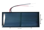
● Solar Panel: Generates DC voltage from sunlight.
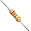
● Resistor: Limits the current to protect the components.
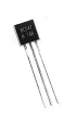
● Photoresistor (LDR): Detects light intensity and controls the transistor.

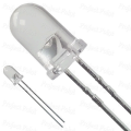
● LED: Indicates the light status.
● Wires: Connect all the components.
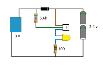
3. Circuit Diagram
The complete circuit diagram shows how the components are connected. The solar panel acts
as the power source, supplying voltage to the circuit. The LDR and resistor are arranged in
series to control the base current of the NPN transistor. When the light level drops, the
transistor is activated, allowing current to flow through the LED, making it glow.
4. Working Principle
1. Solar Power Generation:
○ The solar panel generates electricity when exposed to sunlight.
○ The positive and negative terminals of the panel supply power to the circuit.
2. LDR and Resistor Configuration:
○ The LDR detects the ambient light level.
○ In bright light, the LDR’s resistance decreases, allowing more current to flow to
the base of the transistor.
○ In darkness, the resistance increases, cutting off the base current and turning off
the LED.
3. Transistor Activation:
○ When the transistor receives base current, it switches on, allowing current to
flow from the collector to the emitter.
○ This powers the LED, making it glow.
○ In the absence of light, the transistor turns off, and the LED switches off.
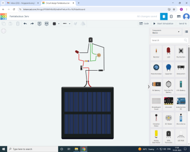
5. Connections in the Circuit
The wiring connections for the circuit are as follows:
1. Solar Panel:
○ Positive terminal → Connected to the collector of the NPN transistor.
○ Negative terminal → Connected to the ground of the circuit.
2. LDR and Resistor:
○ One terminal of the LDR → Connected to the positive rail.
○ The other terminal → Connected to the base of the transistor through a resistor.
3. Transistor:
○ Base → Connected to the LDR-resistor junction.
○ Collector → Connected to the positive terminal of the solar panel.
○ Emitter → Connected to the ground.
4. LED:
○ The LED is connected in parallel to the transistor.
○ It lights up when the transistor is switched on.
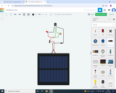
6. Simulation Running
When you run the simulation:
● In bright light, the LED remains off.
● When the light level decreases, the LDR’s resistance increases, triggering the
transistor and turning the LED on.
7. Advantages and Applications
✅ Advantages:
● Automated lighting system based on light intensity.
● Low power consumption due to solar energy.
● Environmentally friendly and cost-effective.
✅ Applications:
● Automatic street lights that turn on at night.
● Solar garden lamps.
● Light-sensitive security systems.
9. Conclusion
The Solar-Powered Light Control Circuit demonstrates the use of renewable energy and
light-sensitive components to automate lighting. It efficiently controls the LED based on the
ambient light intensity, making it ideal for solar-powered automation projects.


Comments
Post a Comment